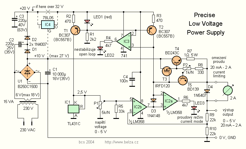
Precise Low Voltage Power Supply Circuit Diagram By changing resistor R2 for a 2k ohm potentiometer we can control the output voltage range of our PSU bench power supply from about 1.25 volts to a maximum output voltage of 10.75 (12-1.25) volts. Then our final modified variable power supply circuit is shown below. Variable Voltage Power Supply Circuit
The performance of a supply commonly used in con-sumer applications - in audio amplifiers, for example - is described in figure 10 and table 1. When a low rippe l voltage is required an LC fltier net-work may be used. The effect on the output voltage of this addition is shown in figure 11. As figure 11 shows, the residual ripple can be reduced Figure 1. A linear regulator converts one voltage into another. For many years, a typical power converter consisted of a 50 Hz or 60 Hz transformer, connected to the power grid, with a certain windings ratio to generate a nonregulated output voltage, a few volts higher than the needed supply voltage in a system.
Variable Voltage Power Supply Using The LM317T Circuit Diagram
However, for achieving a regulated dual power supply with the desired level of dual voltage at the output is something which normally requires a complex design using costly ICs. The following design shows how simply and discretely a dual power supply could be configured using a few BJTs, and a few resistors.

But to test a 300-A, 0.8-V power supply, at least four 63640-80-80 load modules must be combined in parallel—both to achieve an effective on-resistance below 2.7 mΩ and to handle the total current.
The Design Engineers' Guide - Avnet Circuit Diagram
Comparing 5 V with V of supply voltage, used as a reference: 2exp(n) 5 V 3 V . 2exp(-12) 1.22 µV 732 µV. 2exp(-16) 76 µV 46 µV. Voltage regulator devices, such as the REF19x series, are useful in stabilizing supply or reference voltage. They will maintain their output voltage at a constant level until the regulator reaches its "drop-out
